
next[mesh solid] -- current[apply loads] -- next[solve]
Now we have to apply the loadings to our meshed solid. This problem has 1 mounted area and 1 force.
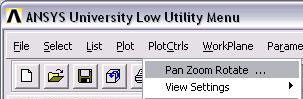
Before we apply forces you should familiarize yourself with the 'pan/zoom/rotate' tool. You can find it under 'PlotCtrls':
It has the basic engineering views as well as buttons for rotating about each axis, and buttons for zooming in and zooming out:
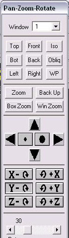
Once you are familiar with this tool, you can continue on to apply forces:
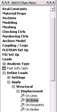
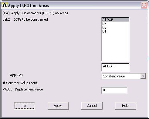
1.) Since the left side of the bracket is mounted it will not displace in any direction. To set this choose 'Define Loads' -> 'Apply' -> 'Structural' -> 'Displacement' -> 'On Areas':
Select the mounted face and click ok [NOTE: you will have to rotate your view so you can easily select this area]:
on the window that pops-up select 'All DOF' and enter a Displacement of 0...the click OK:
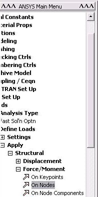
2.) To apply the force select 'Define Loads' -> 'Structural' -> 'Force/Moment' -> 'On Nodes' :
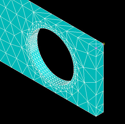
You will apply the forces at the end of the bracket, at the two corners. This will make the loading symmetric about the center plane of the bracket. Select the two node near the end of the bar [NOTE: select 'iso' on the 'pan/zoom/rotate' tool and zoom in a little to easily select a node]:
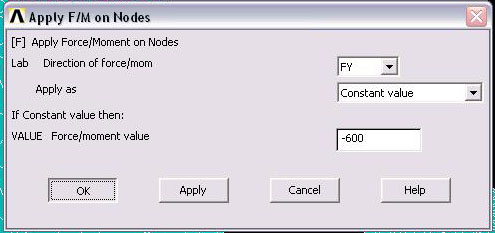
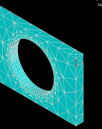
A window will appear asking for the force data. To have a net force of 1200 N, you will need to apply 600 N to each of the nodes you have chosen. Enter the values shown below: Notice a downward force is -600 because the positive y direction points up.
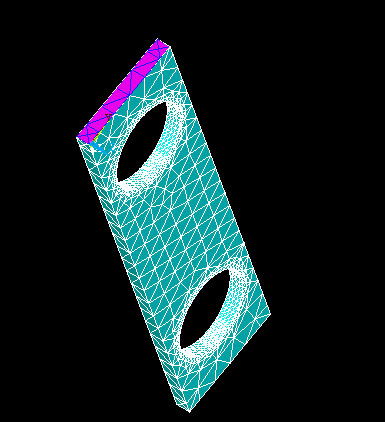
Your bracket should now look like this:
next[mesh solid] -- current[apply loads] -- next[solve]