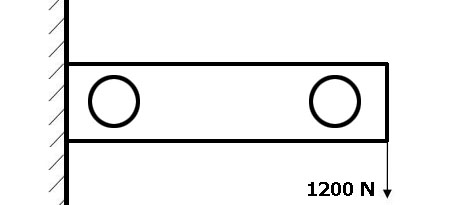
Before importing a SolidWorks part into ANSYS, while still in SolidWorks you must export the part in the IGES file format. Click here if you have not done that yet.
MODEL:
START ANSYS AND IMPORT FILE:
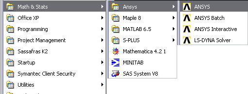
Open ANSYS: on cmu cluster machines its under math & stats:
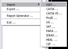
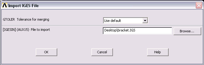
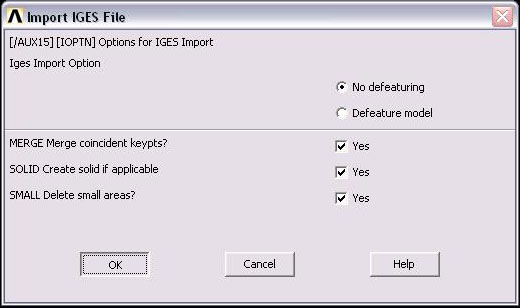
From the file menu select Import>IGES... and select the following options:
|
|
|
Locate your IGS file using the browse button. When you find the file it should look something like this:
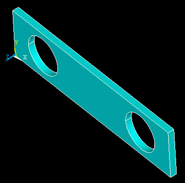
Your screen wll now look like this (notice the axis directions):
MATERIAL PROPERTIES:
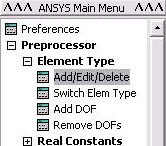
In order for ansys to do a Fine Element Analysis [FEA] we need to specify what kind of element we want to use. For this 3d solid we will be using a 10 node tetrahedron shaped element[solid187]. To set this click on Preprocessor>Element Type>Add/Edit/Delete:
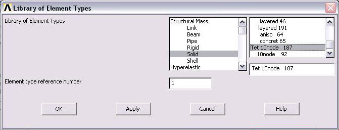
Click 'Add' on the next window(Elements Type) and then find 'Tet 10 node' under 'Structural Mass' -> 'Solids':
click OK and then click Close on the 'Elements Type' window
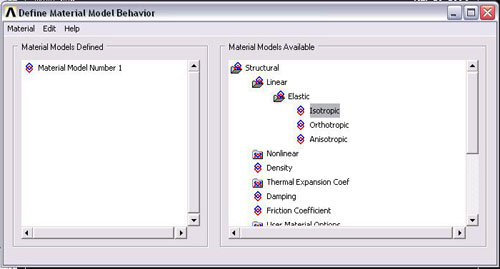
Now we must specify what type of material this solid is. The problem specifies the bracket is to be made of aluminum. To enter material data click on Preprocessor>Material Props>Material Models:
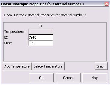
Select Structural>Elastic>Isotropic and enter the following numbers into the window that appears:
EX refers to Young Modulus, which is 7e10 Pa for aluminum
PRXY refers to poisson ratio, which is .33 for aluminum
click OK, then close the Define Material Model Behavior' window
MESHING:
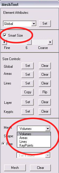
To mesh the volume into individual elements, go to Proprocessor>Meshing>MeshTool:
The MeshTool window will pop-up on the right side of your screen. Select the following options and click 'Mesh':
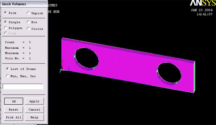
Select the bracket and click ok:
NOTE: If ANSYS gives you an error about going over the maximum number of elements, you must adjust the Smart Size slider to a number higher than 6. The reason for this error is because the educational version limits the maximum number of elements.
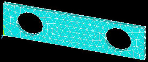
Your mesh should look something like this:
While not necessary to solve the problem, for more accurate results it is often a good idea to add more elements in certain areas of interest. This is called Refining the Mesh and can be done by selecting Preprocessor>Meshing>Modify Mesh>Refine at>Areas:
We are concerned with stresses in the holes so add more elements around the holes by selecting the areas that makes up the 2 holes (4 areas in all).
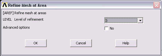
in the next window select 3 and click ok:
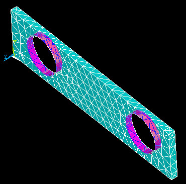
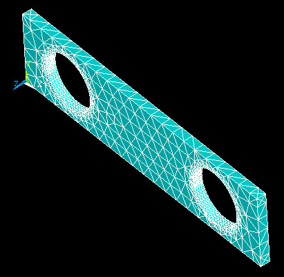
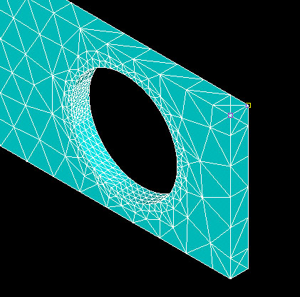
Your mesh will now look like this. Notice there are approximatly three times the elements around the circles:
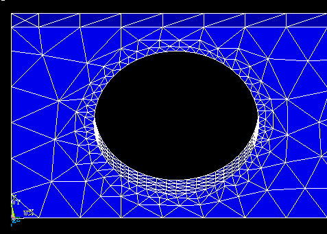
this picture better illustrates the new elements:
BOUNDARY CONDITIONS:
Now we have to apply the loadings to our meshed volume. This problem has 1 mounted area and 1 force.
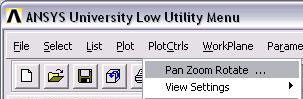
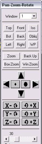
Before we apply forces you should familiarize yourself with the pan/zoom/rotate tool. You can find it under PlotCtrls:
It has the basic engineering views as well as buttons for rotating about each axis, and buttons for zooming in and zooming out:
Once you are familiar with this tool, you can continue on to apply forces
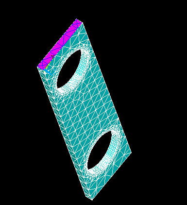
Since the left side of the bracket is mounted it will not displace in any direction. To set this choose Preprocessor>Loads>Define Loads>Apply>Structural>Displacement>On Areas, select the mounted face and click OK (NOTE: you will have to rotate your view so you can easily select this area):
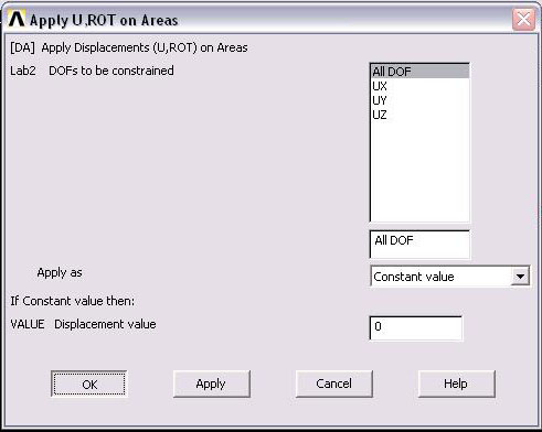
on the window that pops-up select All DOF and enter a Displacement of 0...the click OK:
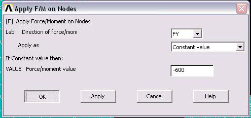
To apply the force select Define Loads>Structural>Force/Moment>On Nodes:
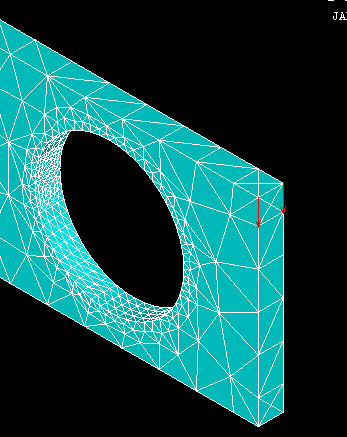
You will apply the forces at the end of the bracket, at the two corners. This will make the loading symmetric about the center plane of the bracket. Select the two nodes near the end of the bar (NOTE: select 'iso' on the 'pan/zoom/rotate' tool and zoom in a little to easily select these nodes):
A window will appear asking for the force data. To have a net force of 1200 N, you will need to apply 600 N to each of the nodes you have chosen. Enter the values shown below: Notice a downward force is -600 because the positive y direction points up.
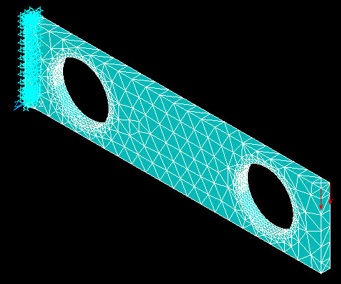
Your bracket should now look like this:
SOLVE:
To run the FEA on the bracket select Solution>Solve>Current LS:
and your bracket will look like this:
POSTPROCESSING:
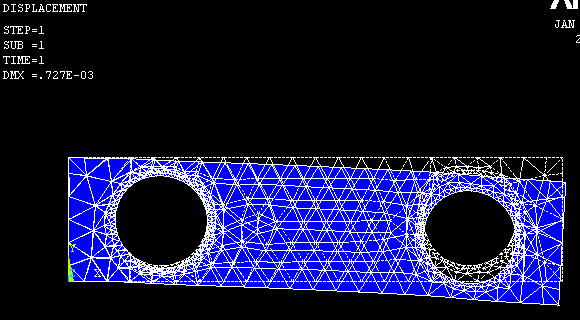
To see the deformed shape of the bracket select General Postproc>Plot Results>Deformed Shape click OK on the window that appears and your bracket should look something like this:
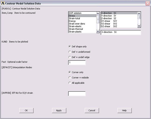
To get various results for the bracket select General Postproc>Plot Results>Contour Plot>Nodal Solu:
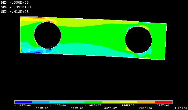
To see the stress in the X direction select the following:
use the 'Pan/Zoom/Rotate' tool to see the 3d stresses. Notice MX and MN locate maximum and minimum stresses
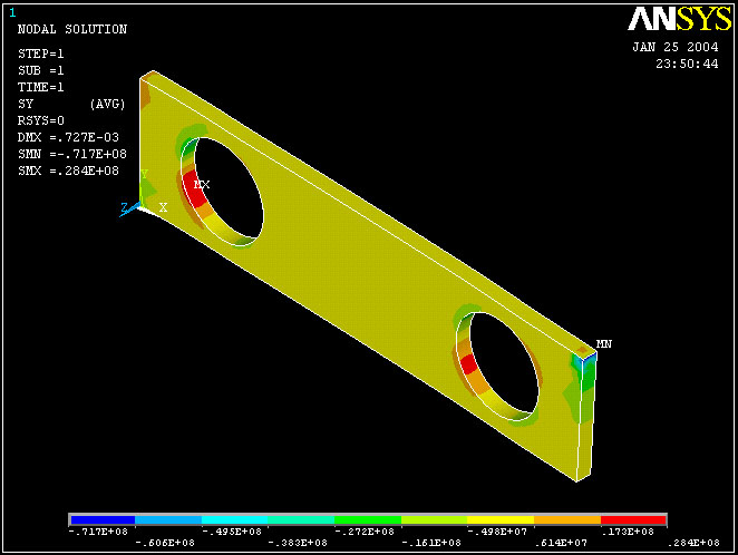
or stress in the Y direction: