Solving Problems with Solidworks:
Checklist for creating mechanisms:
1.) [ ] If your assembly has pins that should be located in specific locations.....Place them using the move component tool and FIX them in place
[ ] Concentric Mate your links to the fixed pins
[ ] Face mate the end of the pins to the side of the links
2.) [ ] If your assembly has objects that must be located in specific locations.....Place them using the move component tool and FIX them in place.
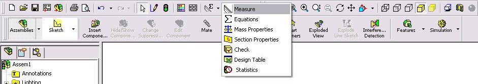
Measure Tool: The Measure Tool is used to get the distance between points, the angle between lines, the displacement of parts in an assembly, and anything else you would use a ruler or protractor for in real life. To open the Measure Tool you can select it from: Tools->Measure...
Or you can select the measure tool using the Tools Button on the main toolbar:
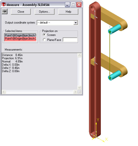
Using the tool is very simple. You can select points or lines and it gives you information regarding the two selected entities. Pay particular attention to delta x, y, and z values. It allows you to determine distance between points independently from the global origin:
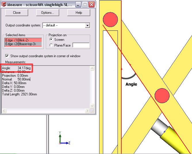
To measure the angle between 2 parts you must select 2 intersecting lines or edges on those parts. Look at the following picture for clarification(the 2 red edges were selected):
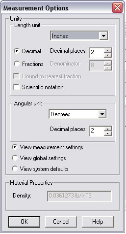
To change the units for display, click the Options... button and use the drop down menu to select the units you want:
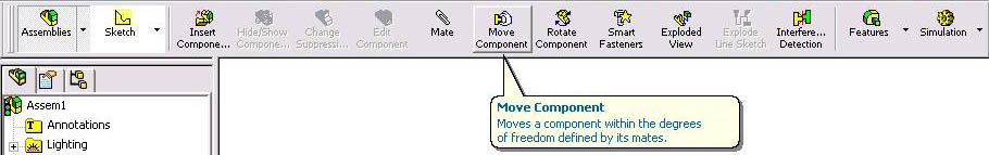
Move Component: It is often important to be able to move a part in an assembly by a specified displacement or angle or to a specific xyz coordinate. The move component tool can be used for this if you understand how to properly use the tool. It is located on the main toolbar:
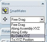
The Move Component tool has the following options (they are explained in detail below):
1.) Free Drag option is the default and it allows you to drag the selected part wherever you want. It is useful for positioning parts for mates or for moving assemblies. It is not useful for accurate movement.
2.) Along Assembly XYZ is an inaccurate method of moving a part in exclusively the x y or z direction.
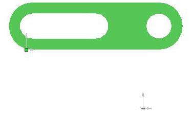
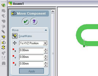
3.)Move to XYZ position: This is useful if you want to move a point on a part to a specific xyz coordinate. Consider the following link, which is located somewhere random in space.
To move the link to the origin, first select a point on the link. (Notice that the origin is below the selected point and to the right at the location 0,0,0)
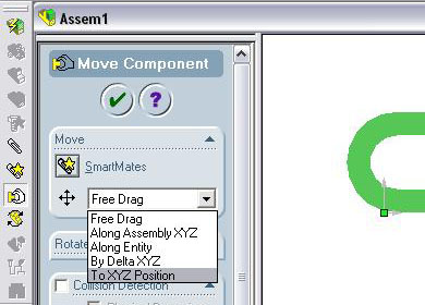
Next click the Move
Component button
![]() on the assembly toolbar and select 'To XYZ Position.'
on the assembly toolbar and select 'To XYZ Position.'
|
Now the the point on the link is at the origin of the assembly:
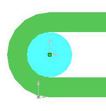
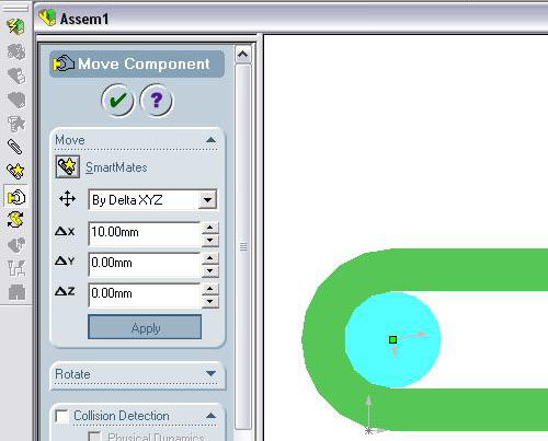
4.) Move by delta XYZ: This is useful when you want to move a part a specific distance relative to its current location. You can choose to move by any combination of x, y and z distances as long as the part is not fixed or restrained by a mate. In this example, move a pin in a slot by 10mm to the right. Note that since the pin is mated to the inside of the slot you cannot move it in the y or z directions.
The first step is to select a point on the pin, or the pin itself:
Next click the
Move Component button
![]() on the assembly toolbar and select 'By delta XYZ.'
on the assembly toolbar and select 'By delta XYZ.'
Change the value in deltaX to 10mm and hit apply:
Now the pin has moved 10mm to the right:
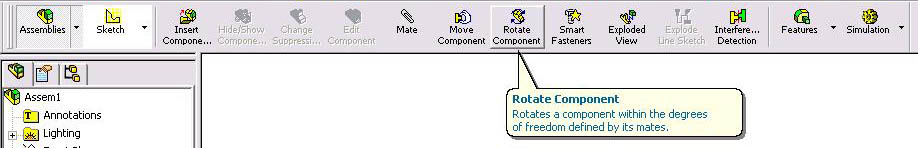
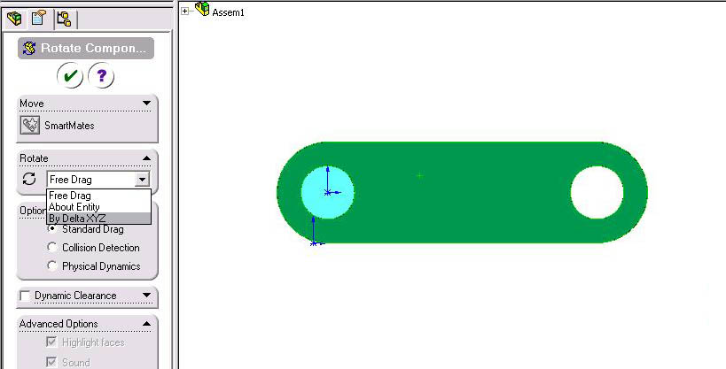
Rotate Component: It is often important to be able to rotate a component in an assembly by a specific angle about the x y or z axis. The rotate component tool can be used for this if you understand how to properly use the tool. It is located on the main toolbar:
In this example the green link will be rotated around the pin by 45 degrees in the positive z direction. To do this, click the Rotate Component button. In the window that appears to the left of the assembly, use the drop down list to select 'By Delta XYZ'
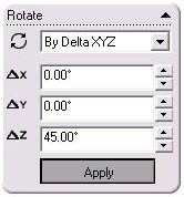
Enter 45 into the Z text box and click apply:
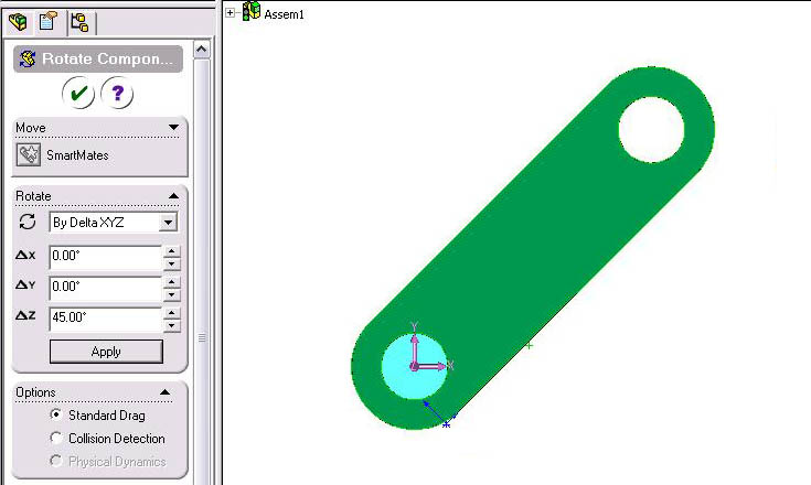
The link will rotate 45 degrees and stop:
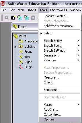
Select 'Tools' -> 'Options.' On the 'Document Properties' window select 'Units' and change them to whatever you want:
 |
 |
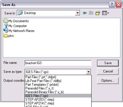
Exporting to ANSYS: ANSYS uses a different file format from SolidWorks but it can still read SolidWorks parts as long as you first convert them to the IGES[Initial Graphics Exchange Specification] format.
1.) After saving the file in SolidWorks as the usual .sldprt file, and while that file is still open in SolidWorks, select 'File' -> 'Save As...' and change 'Save as Type' to 'IGES File (*.igs)':
2.) Click Options in the 'Save As' window and change 'Surface Representation' to 'ANSYS':
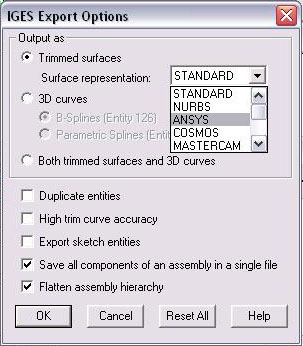
3.) click 'OK' and then 'Save'
click here to import model into ANSYS
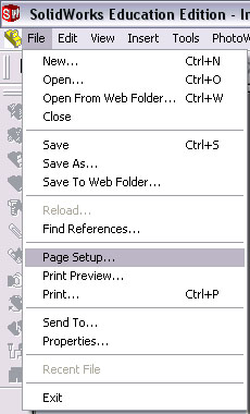
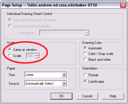
Printing: To print what you see on the screen you have to change a setting in page setup. 'File' -> 'Page Setup'.
Otherwise the printout will be the actual size of the part you are working with. In some cases this is larger than a piece of paper.
 |
 |