
PLANAR JOINTS:
NOTE: if you are not familiar with the layout of SolidWorks, then click here to familiarize yourself with the layout. If you are unfamiliar with assemblies please see the assembly tutorial.
There are three types of Planar Joints: Pin Joint, Pin-in-Slot, and Sliding. Solidworks will allow us to study these joints in a way that a simple drawing or schematic would not allow. We will be able to actively move the joints and see the limitations of each joint type.
This tutorial uses files in the parts.zip package. Make sure you download and extract the files to your computer. The assemblies in this tutorial come from the "planar joints" directory. RED pins represent pins that are fixed from translating...each still allows rotation of the body connected to it.
The first Planar Joint is called a Pin Joint. It is one you are already familiar with since it can be seen in most mechanical systems.
It only permits two bodies to pivot relative to another.
As an example of a pin joint consider a scissors lift shown below. This mechanism, which serves to raise platform holding workers, has a series of links which are unfolded by several hydraulic cylinders. Each pair of links is connected by a pin joint which enables them to pivot with respect to each other:
 |
 |
To examine a simple pin joint in solidworks, follow these steps:
1.) Goto File->Open and select "pinjoint.SLDASM" from the planar joints folder
2.) using the rotate component
button
![]() and the move component button
and the move component button
![]() see
how the pin joint moves in space. Notice the limitations of this joint:
see
how the pin joint moves in space. Notice the limitations of this joint:
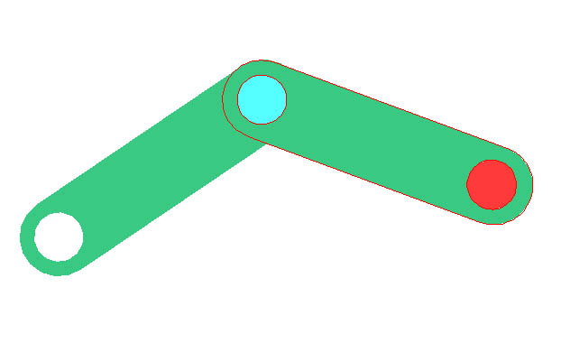
You can see that there are actually two pin joints in this assembly. The pin in a pin-joint could be fixed in position, or it can join two parts, both of which can move.
The second Planar Joint is called a Pin-in-Slot joint. A pin-in-slot joint allows the joined bodies to pivot with respect to each other and to translate with respect to each other in one direction. However translation in the perpendicular direction is restricted.
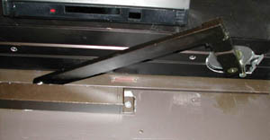
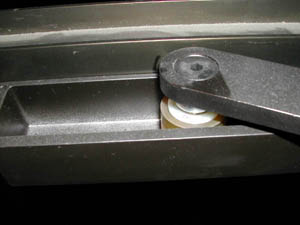
As an example of a pin-in-slot joint, consider the motorized door opener shown. The end of one member has a pin with a roller, which rolls in a slot in the door:
 |
 |
To examine a simple pin-in-slot joint in solidworks, follow these steps:
1.) Goto File->Open and select "pininslot.SLDASM" from the planar joints folder
2.) using the rotate component
button
![]() and the move component button
and the move component button
![]() see
how the pin-in-slot joint moves in space. Notice the limitations of this
joint:
see
how the pin-in-slot joint moves in space. Notice the limitations of this
joint:
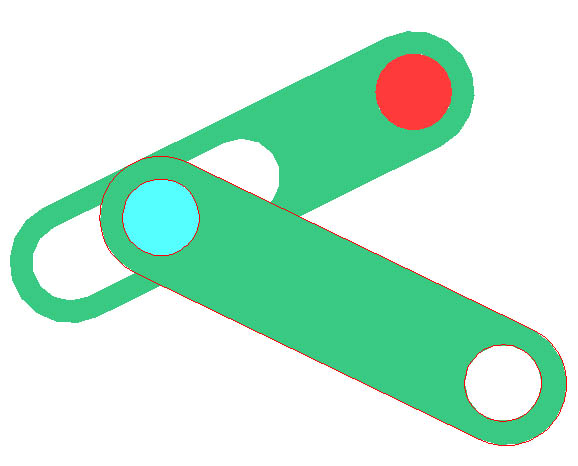
You can see that the link with a slot and a hole is pinned at its hole to some fixed body which is not shown, but that a second link is connected to the slot with a pin. The pin-in-slot joint is that connecting the two links.
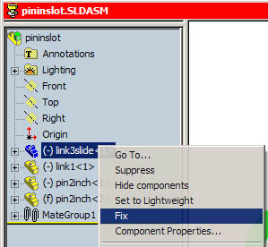
ALSO: Notice that you can only translate the link with two holes, not rotate it. This is a limitation of Solidworks. A work around to this problem is to "fix" the link in space by right clicking on link3slide in the Feature Manager Design Tree and click "Fix":
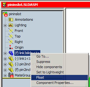
You may get a message that the assembly cannot be solved with this mate. However, you will find that it probably works. Now the link with two holes can be both translated and rotated. You can return to the initial state in which the slotted link floats by right clicking on link3slide in the Feature Manager Design Tree and selecting "Float":
The third Planar Joint is called a sliding joint. A sliding joint prevents two bodies from rotating with respect to one other and permits the bodies to translate with respect to one another only in a single direction.
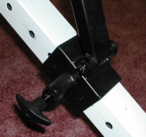
As an example of a sliding joint, consider the mechanism for adjusting the position of the back to the exercise machine. The black sleeve can only slide on the white member. Notice that the sleeve is locked into position by the spring loaded pin (with the black handle) which engages one of the holes in the white member. But when this pin is retracted, the sleeve can slide. Notice that another link is pinned to the sleeve:
 |
 |
To examine a simple pin-in-slot joint in solidworks, follow these steps:
1.) Goto File->Open and select "slidingjoint.SLDASM" from the planar joints folder
2.) using the move component
button
![]() see
how the sliding joint moves in space. Notice the limitations of this
joint:
see
how the sliding joint moves in space. Notice the limitations of this
joint:
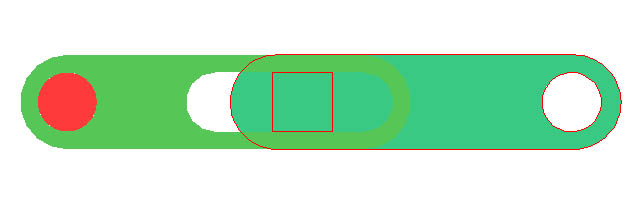
You can see that a link with a slot and a hole is pinned at its hole to some fixed body which is not shown. A second member with a square peg engages the slot. While the link with the slot can pivot about its pin joint, the second member can only slide in one direction relative to the slotted link. The sliding joint is that connecting the two links.