Using Planar Joints to Form Mechanisms:
NOTE: if you are not familiar with the layout of SolidWorks, then click here to familiarize yourself with the layout. If you are unfamiliar with assemblies please see the assembly tutorial.
By connecting members of various shapes and sizes with planar joints, the motion (input) of one body brings about the desired (output) motion of another body. Two common input motions are: rotation of a shaft (by a motor) and translation of a body (by actuating a hydraulic or pneumatic cylinder). These are also two commonly desired output motions: pivoting a body about a point and translating a body along a line.
However, the input body often cannot be attached directly to the output body. Therefore, a mechanism converts the input motion to the output motion.
To illustrate this effect, we show three mechanisms which accomplish the same purpose: pivoting a member about a point. The member could be a door pivoting about its hinge:
This tutorial uses files in the parts.zip package. Make sure you download and extract the files to your computer. The assemblies in this tutorial come from the "pivot" directory. RED pins represent pins that are fixed from translating...each still allows rotation of the body connected to it.
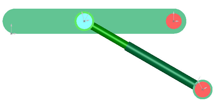
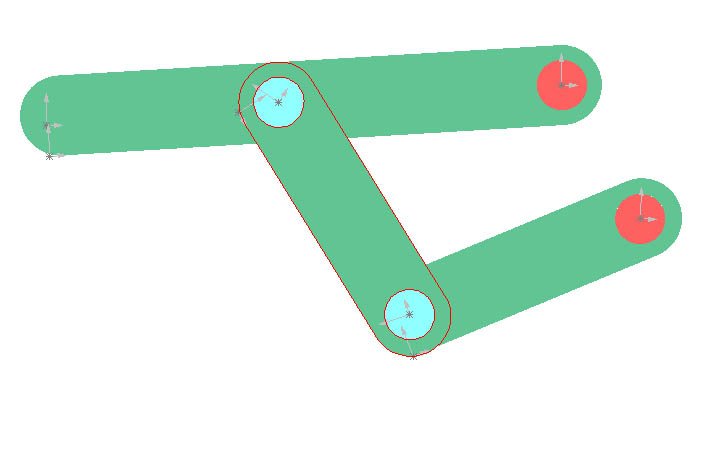
Method 1 (Pivot1.SLDASM)
The pivoting member (top) is acted upon by a link (middle), which is in turn driven by a second link (bottom). The bottom link is pivoted by a motor. The motor is not shown, but the shaft of the motor (shown here as a fixed pin) would engage the link causing it to turn. Besides the hinge of the top green member (which is like the hinge of a door), this method involves two pin joints. The mechanism at work here is called a four bar linkage. The "fourth" link joins the two red dots. In the four bar linkage, one link always joins the two fixed pins.
Method 2 (Pivot2.SLDASM)
The pivoting member (top) has a slot in which a pin (blue) slides. The pin is connected to an L-shaped member. The L-shaped member would be pivoted by a motor just as the bottom link above is pivoted by a motor. Besides the hinge of the top member, this method involves a pin in slot joint.

Method 3 (Pivot3.SLDASM)
The pivoting member (top) is acted upon by the piston of a hydraulic (or pneumatic) cylinder. The hydraulic cylinder case is connected to a fixed pin about which it can pivot. The piston is moved back and forth in the case by the flow of compressed fluid or air. As the cylinder extends or contracts, the top member pivots about its pin. Besides the hinge of the top member, this method involves a sliding joint and two pin joints. (The piston and case are connected by a sliding joint.) The mechanism at work here is an inverted version of the crank and slider mechanism.