
MODIFYING PARTS:
NOTE: if you are not familiar with the layout of SolidWorks, then click here to familiarize yourself with the layout
This tutorial will use "link3slide.SLDPRT" from the parts.zip file. You can use these techniques on any part though. The steps in this tutorial are similar to the steps in the dimensioning tutorial. The more you understand solidworks the more you realize that even the most complex parts are made and changed in a similar fashion to the steps in these tutorials.
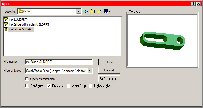
1.) Use file->open and browse to the links folder. Select "link3slide.SLDPRT" and click open:
2.)
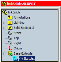
You can only add features in sketch mode. To enter sketch mode
you must first decide where you want to add the feature. You can add a feature
to any plane. You can
usually find the sketch under an "extrude" in the
feature manager design tree. You will have to click the
![]() to reveal the sketch:
to reveal the sketch:
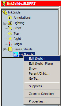
3.) Right click on the sketch and select ‘edit sketch.’ You will notice that the rest of the part disappears or becomes transparent. Do not worry if some of the features of the part become transparent or disappear. They have NOT been deleted. They have simply been removed to simplify the screen and highlight the sketch you are currently working with. See the advanced dimensioning tutorial for an example of "disappearing" parts:
4.) You will now be in sketch mode and can use all the buttons on the right of the screen (picture rotated to save space):
![]()
5.) If your view of the part is skewed, click the front view on the standard view menu to rotate the sketch (view->toolbars->standard view):
![]()
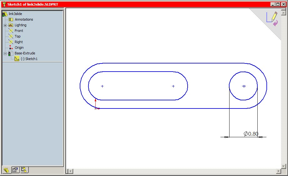
6.) Your window should now look like this:
7.) To add another hole to the link select "draw circle" from the sketch toolbar:
![]()
8.) The cursor changes and you can now draw a circle on the link:
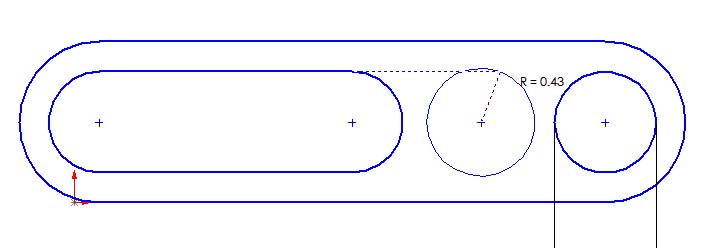
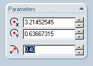
9.) to edit the radius of the circle either follow the steps in the dimensioning tutorial or modify the radius in the feature manager design tree:
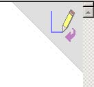
10.) Exit sketch mode by clicking the purple arrow in the top, right hand corner:
11.) The new hole will be cut out of the link and your link should now look like this:

12.) To remove the hole you re-enter edit sketch mode. Do this by right clicking on the sketch and selecting edit sketch:
13.) Select the hole you just created by clicking on it with your mouse and hit the delete key on your keyboard. The hole will disappear. Exit sketch mode by clicking on the purple arrow:
You are now ready to try Modification Exercise 1
If you want to modify any extrusion follow this example:
1.) Use file->open and browse to the links folder. Select "link3slide.SLDPRT" and click open:
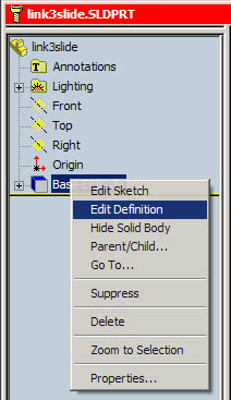
2.) Right click on "Base-Extrude" in the Feature Manager Design tree and click "Edit Definition":
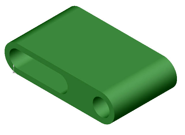
3.) You will be presented with extrusion options. In this example change the Depth dimension from 1.00in to 3.00in and click the green check mark:
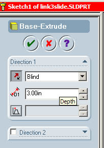
4.) The link will now be three times thicker:
You are now ready to try Modification Exercise 2
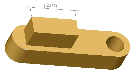
for more practice try adding a square hole to the same link:

starting with "linkwithsquareboss.SLDPRT" stretch the boss to 2 inches:
NOTE: make sure you are familiar with the dimensioning tutorial
Troubleshooting:
● If you mess up badly, you can always edit->undo.
Likewise, if you want to go back to a certain point, you can use the undo list
![]() to see your undo options
to see your undo options