DIMENSIONING:
NOTE: if you are not familiar with the layout of SolidWorks, then click here to familiarize yourself with the layout
Like all CAD programs, SolidWorks allows you to dimension the parts you create. Parts do not have to be dimensioned, but when you are making accurate drawings or are interested in mating parts, dimensions are extremely important. Luckily, SolidWorks makes it very easy to add and change dimensions. This tutorial will use "link3slide.SLDPRT" from the parts.zip archive. You can use this tutorial for any part though.
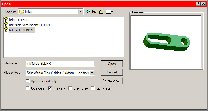
Use file->open and browse to the folder that you downloaded the file to. Select "link3slide.SLDPRT" and click open:
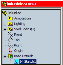
You can only edit dimensions in sketch mode. To enter sketch mode
you must first determine which sketch contains the dimension to change. Locate
the sketch which contains the line/circle/arc you want to dimension. You can
usually find the sketch under an "extrude" in the
feature manager design tree. You will have to click the
![]() to reveal the sketch:
to reveal the sketch:
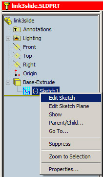
Right click on the sketch and select ‘edit sketch.’ You will notice that the rest of the part disappears or becomes transparent. Do not worry if some of the features of the part become transparent or disappear. They have NOT been deleted. They have simply been removed to simplify the screen and highlight the sketch you are currently working with.
You will now be in sketch mode and can use all the buttons on the right of the screen (picture rotated to save space):
If your view of the part is skewed, click the front view on the the standard view menu to rotate the sketch:
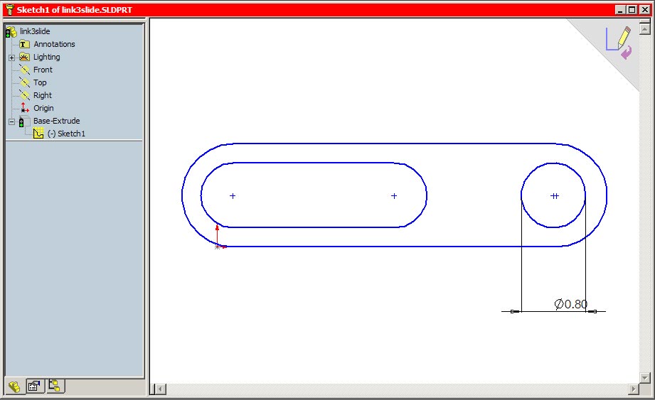
Your window should now look like this:
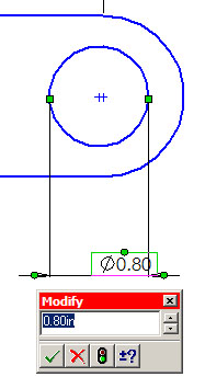
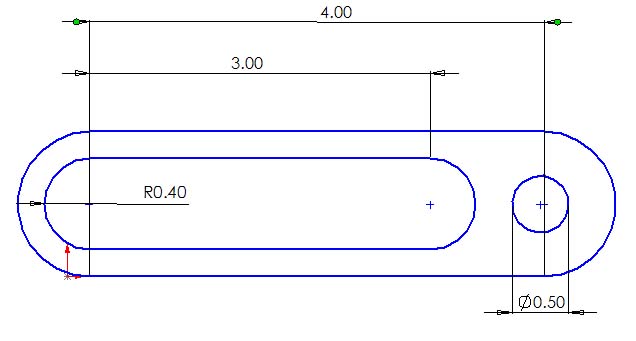
We will now edit the diameter of the circular hole. We will edit it because the hole already has a dimension (.80in). This is specified by the lines coming off the circle with .80 on the bottom. To edit the dimension DOUBLE-CLICK on the .80. A box labeled "Modify" will appear.
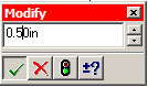
Erase .80 and enter .50. Click the green check or press enter.
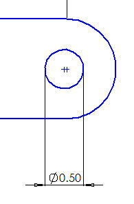
Notice the hole gets smaller:
Editing Dimensions is great if dimensions are already defined in the sketch. But what if we want to add new dimensions? We will now learn how. First make sure you are in sketch mode. Follow the directions above if you are no longer in sketch mode. Notice that when you move your cursor over the sketch that certain features turn red. Any feature that turns red can be dimensioned. These features are:
- a circle radius or diameter
- a line
- an arc
- a fillet/chamfer
- distance between two points
- distance between a line and a point
To add a dimension click the dimension button
![]() found on the sketch tools toolbar on the right of the screen. You will
notice the cursor changes to
found on the sketch tools toolbar on the right of the screen. You will
notice the cursor changes to
![]() when
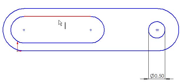
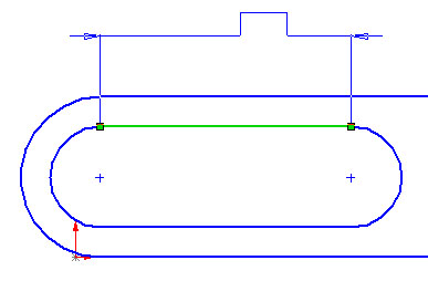
you do this. We will now dimension the length of the slot. Move your cursor over
the slot until either the top or bottom line turns red.
The cursor will change again to
when
you do this. We will now dimension the length of the slot. Move your cursor over
the slot until either the top or bottom line turns red.
The cursor will change again to
![]() signifying a line that can be dimensioned:
signifying a line that can be dimensioned:
When it does, click with the left mouse button and drag up or down to select the placement of the leader and dimension. The placement is not critical. It is usually best to place it out of the way to keep the sketch neat and readable. When you are satisfied with the placement left-click again:
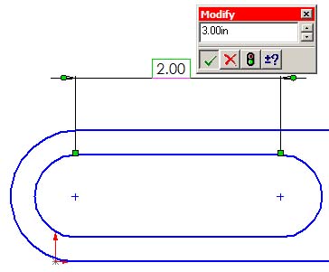
You can now edit the dimension exactly like above. Enter 3.00 and click the green arrow or press enter:
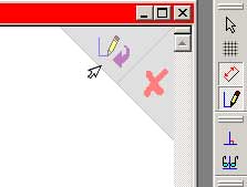
When you are done dimensioning, make sure to exit sketch mode by clicking the arrow in the top right corner of the screen:
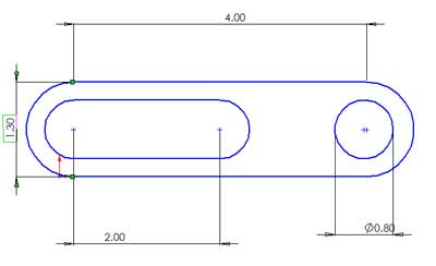
You are now ready to try Dimensioning Exercise 1
Try adding the following dimensions for more practice:
Troubleshooting:
● If you notice that the dimension tool is not working or working erratically, you can always hit escape to unselect the dimension tool and start over again. This usually fixes any problem.
● If you mess up badly, you can always edit->undo.
Likewise, if you want to go back to a certain point, you can use the undo list
![]() to see your undo options
to see your undo options