|
Truss Bending Analysis:
Introduction:
In this example you
will learn to use the 2-D Spar element in ANSYS to analyze trusses.
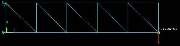
Physical Problem:
A truss
structure deflects under load.
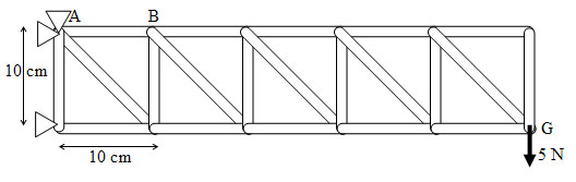
Problem Description:
·
The
truss structure is made up of two-force members. Each two force member
only experiences loading in the axial direction.
·
Units: Use S.I. units ONLY
·
Geometry: the cross sections of each of the truss
members is 6.25e-6 (m2).
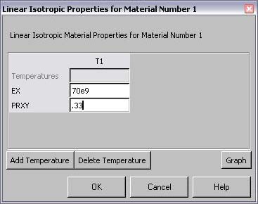
·
Material: Assume the structure is made of aluminum with modulus of
elasticity E=70e9 (N/m2) and Poisson ratio 0.33.
·
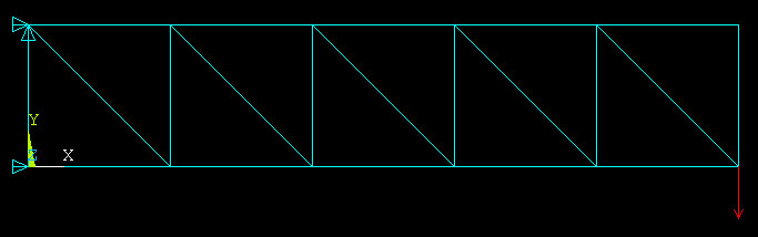
Boundary
conditions: The structure is constrained along X and Y directions at the
left top end, and along the X direction at the bottom left corner.
·
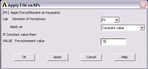
Loading:
The structure is loaded at the bottom right corner. with a vertical
force acting downward with magnitude 5 N.
·
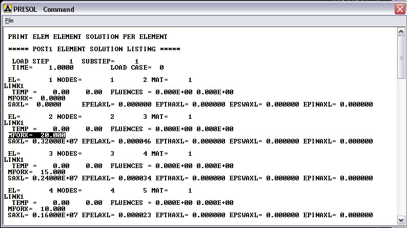
Objective:
o
To
determine the force in member AB.
o
To
determine the downward deflection at G
·
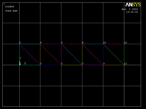
Figure:
The horizontal
and vertical truss members are all .1m long.
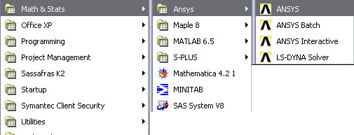
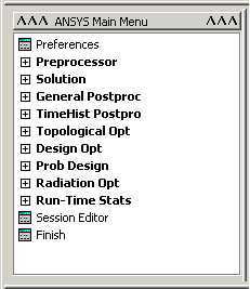
STARTING ANSYS
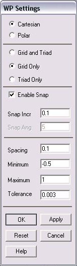
MODELING THE STRUCTURE
-
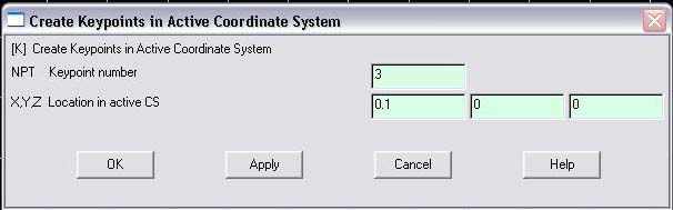
Another way of
picking Keypoints is by manually entering the coordinates. This is
more useful for 3d structures, but it is worth noting here anyway...
o
Click
Preprocessor>Modeling>Create>Keypoints>In
Active CS
o
Choose a number for each Keypoint, say 1,2,3…
o
enter coordinates for each Keypoint:
MATERIAL PROPERTIES
-
Go to the ANSYS
Main Menu
-
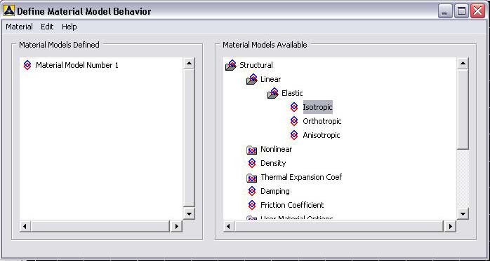
Click
Preprocessor>Material Props>Material Models.
-
In
the window that comes up which is shown below, for Material Model 1,
choose
Structural>Linear>Elastic>Isotropic.
ELEMENT PROPERTIES
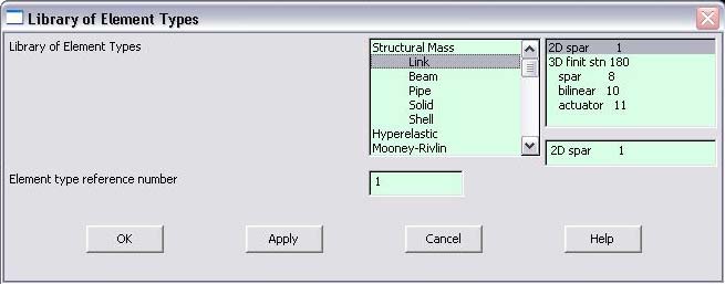
-
Click on Structural
Link and select 2D spar. Click OK. Close the 'Element types' window.
-
So now we have
selected Element type 1 to be a structural Link- 2D spar element. The
trusses will be modeled as elements of type 1, i.e. structural link
element. This finishes the selection of element type.
-
Now we need to
define the cross sectional area for this element.
-
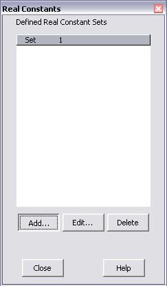
Go to
Preprocessor>Real Constants
-
In the "Real
Constants" dialog box that comes up click on Add
-
In the "Element
Type for Real Constants" that comes up click OK. The following window
comes up.
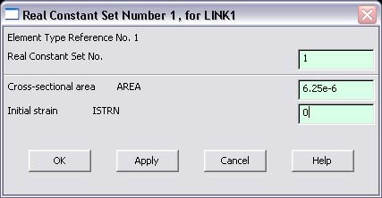
-
Type 6.25e-6
for cross sectional area of Element Type Reference number 1 and click on OK.
-
While not needed
for this specific problem, if you wanted to add
different cross sectional areas to your structure you have to define
multiple real constants.
-
Go to
Preprocessor>Real Constants
-
-
Click add
and enter the cross section area the same way as before. Make sure
the Real Constant Set No. box is incrementing by 1 each time you add
a real constant. The next section will show you how to set each
element's cross section area
MESHING:
-
DIVIDING THE
STRUCTURE
INTO ELEMENTS:
-
Go to
Preprocessor>Meshing>Size Cntrls>ManualSize>Lines>All
Lines.
-
In the menu that
comes up type 1 in the field for 'Number of element divisions'. This
divides each of the lines in your figure into 1 element.
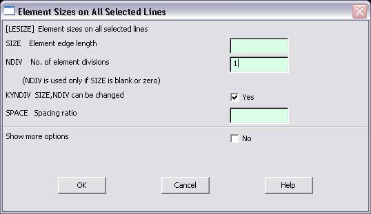
-
Click on OK.
-
Now
go to
Preprocessor>Meshing>Mesh>lines
-
Select all the
lines and click on OK in the "Mesh Lines" dialog box.
-
Now each line is a
truss element (Element 1).
-
This is not necessary for this problem,
but if you specified multiple real constants
above (if your structure has multiple cross sectional areas) you have
to tell ANSYS which elements have which area:
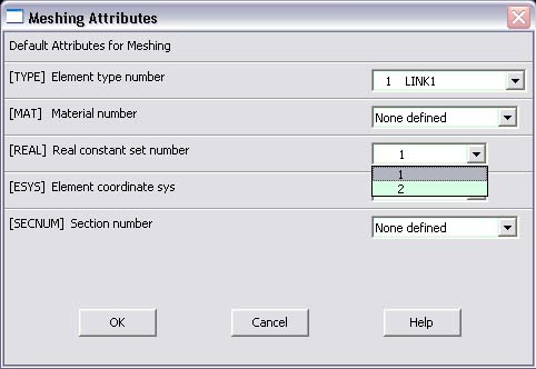
-
Go to
Preprocessor>Meshing>Mesh Attributes>Default Attribs
-
Here you can choose
which real constant to use when specifying the mesh. For
example...choose element 2
-
-
Now
go to
Preprocessor>Meshing>Mesh>lines
-
Select all the
lines you want to have the cross section of real constant 2 and click on OK in the "Mesh Lines" dialog box.
-
Repeat this process for all of your
real constants
BOUNDARY CONDITIONS AND CONSTRAINTS
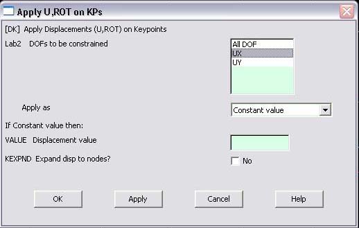
-
Select UX and UY
for the top left corner. The default displacement value is taken to be
zero
-
Repeat this
procedure for the bottom left corner but only constrain UX.
-
APPLYING FORCES
-
Go to Main Menu.
-
Click
on
Preprocessor>Loads>Define Loads>Apply>Structural>Forces/Moment>On
Nodes.
-
Select the bottom
right
node.
-
Click on OK in the
'Apply F/M on Nodes' window. The following window will appear.
SOLUTION
-
Go to
Solution>Solve>Current LS.
-
Wait for ANSYS to
solve the problem.
-
Click on OK and
close the 'Information' window.
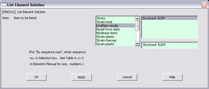
POST-PROCESSING
|