WORKING WITH PARTS IN SOLIDWORKS:
NOTE: if you are not familiar with the layout of SolidWorks, then click here to familiarize yourself with the layout

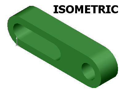
SolidWorks allows you to view 3d parts from all different angles. There are infinite ways to view an object, but engineers usually only concern themselves with 4 main views. You can see these views in the above picture of the green link. The main views are Side, Front, Top, and Isometric.
For this tutorial you can open up any part in Solidworks. The tutorial will use the green link above to demonstrate, but any 3d part will work just as well. This link can be found in the parts.zip archive
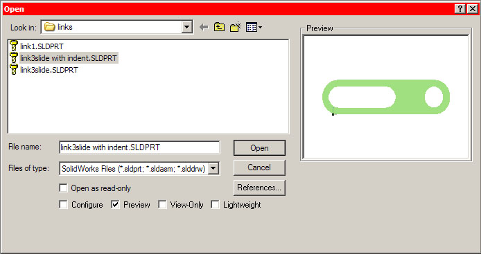
Start SolidWorks and goto file>open
Find your part and click open.
Viewing the Part:
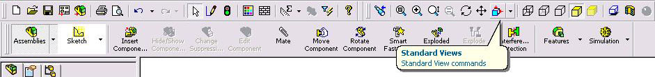
You can access the standard engineering views by clicking the Standard Views button on the main toolbar:
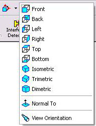
Each small box on the "Standard View" menu corresponds to a view of the object. The best way to understand what each view means is to click each view and see what happens.
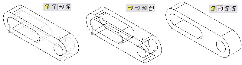
Below is a front, back and isometric view of the link:
|
|
 |
|
|
|
You can select a
non-shaded view using the "View" toolbar:
![]() and by clicking on the non-shaded box(with hidden lines)
and by clicking on the non-shaded box(with hidden lines)
![]() .
There is also an option for non-shaded without hidden lines, and non-shaded with
solid hidden lines:
.
There is also an option for non-shaded without hidden lines, and non-shaded with
solid hidden lines:
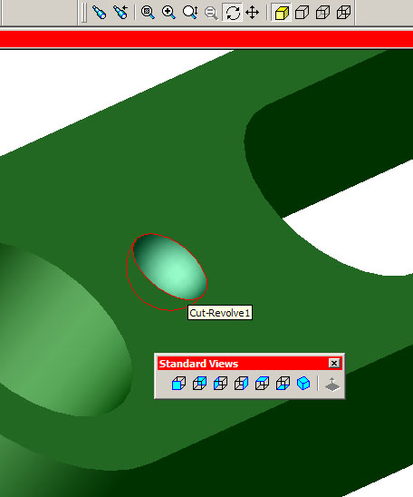
What if we want to view the indent in more detail? The
standard views do not give a good view of it. Sometimes the only way to get a better look
of a part or feature is to control the view manually. Use the rotate
![]() and zoom
and zoom
![]() tools to get a better view of the indent. NOTE: if you
have a mouse with a scroll wheel, you can rotate and zoom without these buttons.
Push down on the wheel to rotate, and spin the wheel to zoom in and out:
tools to get a better view of the indent. NOTE: if you
have a mouse with a scroll wheel, you can rotate and zoom without these buttons.
Push down on the wheel to rotate, and spin the wheel to zoom in and out:
Extracting Dimensions From the Part:
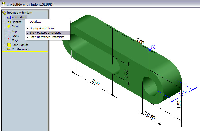
The simplest method of extracting the dimensions of a part is to make the dimensions visible in the default view:
Right click where it says annotations on the feature manager design tree, and click where it says 'Show Feature Dimensions':
If there is a check mark next to 'Show Feature Dimensions,' all the defined dimensions will appear.
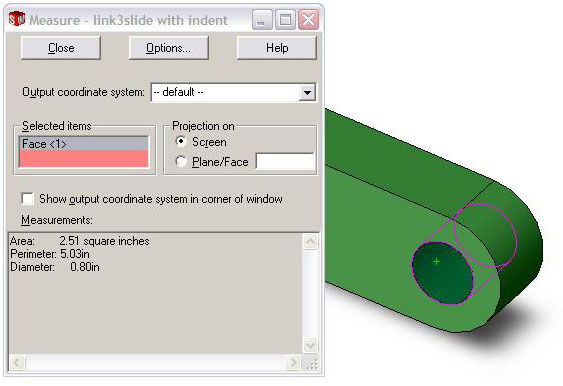
Another method of extracting the dimensions of a part is to use the Measure Tool:
Go to the main file menu and select Tools>Measure. The cursor will change to a ruler and a dialog box will appear with the title 'Measure.' Switch to Isometric View and then click the circular hole. The Measure Tool window will display all the properties of this hole:
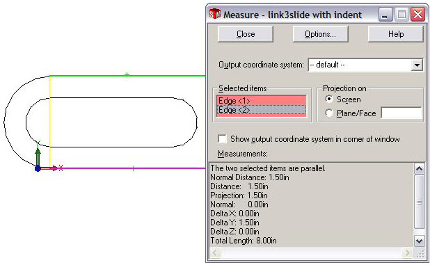
Likewise, you can use the measure tool to measure the distance between any 2 lines. For example, the distance between the top and bottom of the link from the side is 1.50 inches (shading turned off for clarity):
Another method to extract dimensions of the link is to use the sketch mode. This will be most useful later on when we are interested in changing dimensions:
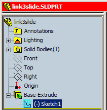
Goto the feature manager design tree and locate
'Base-Extrude.' Click the
![]() to reveal the sketch.
to reveal the sketch.
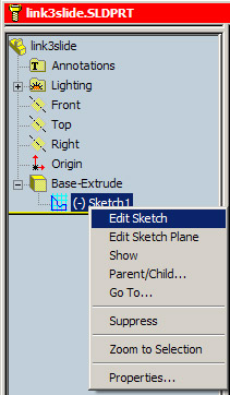
Right click on 'Sketch1' and select ‘edit sketch.’
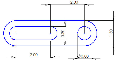
The view will change and you will now see a 2d drawing with all the dimensions:
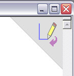
To exit sketch mode click the purple arrow in the top, right corner, or right click in the drawing area and select 'exit sketch':
the assembly tutorial continues ideas from this tutorial